• - Creates View Section co-planar
to XY plane of current UCS by defining point and View Section
Thickness. You can create View Section by defining point on XY plane of
current UCS (work plane). The thickness of View Section is defined in
Thickness (m) field, when you slide out Create panel by clicking
on its title bar;
- Creates View Section co-planar
to XY plane of current UCS by defining point and View Section
Thickness. You can create View Section by defining point on XY plane of
current UCS (work plane). The thickness of View Section is defined in
Thickness (m) field, when you slide out Create panel by clicking
on its title bar;
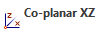
• - Creates View Section co-planar
to XZ plane of current UCS by defining point and View Section
Thickness. You can create View Section by defining point on XZ plane of
current UCS (work plane). The thickness of View Section is defined in
Thickness (m) field, when you slide out Create panel by clicking
on its title bar;
- Creates View Section co-planar
to XZ plane of current UCS by defining point and View Section
Thickness. You can create View Section by defining point on XZ plane of
current UCS (work plane). The thickness of View Section is defined in
Thickness (m) field, when you slide out Create panel by clicking
on its title bar;
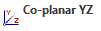
•- Creates View Section co-planar
to YZ plane of current UCS by defining point and View Section
Thickness. You can create View Section by defining point on YZ plane of
current UCS (work plane). The thickness of View Section is defined in
Thickness (m) field, when you slide out Create panel by clicking
on its title bar;
• - Creates View Section for
statistical Point cloud surface;
- Creates View Section for
statistical Point cloud surface;
• - Creates View Section by
selected line;
- Creates View Section by
selected line;
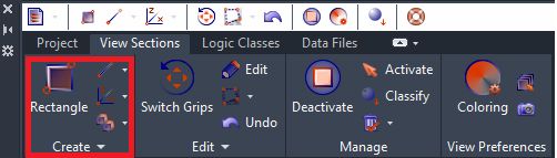
•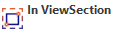 - Creates rectangular View
Section in active View Section (extends are taken from the active View Section);
- Creates rectangular View
Section in active View Section (extends are taken from the active View Section);
• - Creates View Section by
defining Line and View Section Thickness. You can create View
Section by defining two points on the screen plane. The thickness of section is
defined in Thickness (m) field, when you slide out Create panel by
clicking on its title bar or just enter thickness value in command
line;
- Creates View Section by
defining Line and View Section Thickness. You can create View
Section by defining two points on the screen plane. The thickness of section is
defined in Thickness (m) field, when you slide out Create panel by
clicking on its title bar or just enter thickness value in command
line;
• - Creates View Section by
defining Box. There are two ways of creating View Section with
Box:
- Creates View Section by
defining Box. There are two ways of creating View Section with
Box:
o The base of the Box is drawn parallel to the XY plane of the current UCS (work plane). The height of the Box is specified in the Z-axis direction. You can enter both positive and negative values for the height;
o You can specify Box parameters by entering only two diagonal points of the Box. In this case it would be helpful to turn on Node Object Snap to bind Box diagonal points to PC Object’s points.
• - Creates box View Section by
defining its middle point;
- Creates box View Section by
defining its middle point;
• - Defines View Section by
rectangle;
- Defines View Section by
rectangle;
• - Creates a copy of Active View
Section;
- Creates a copy of Active View
Section;
• - It will multiply your initial
View Section through the AutoCAD’s 3D Array Rectangle;
- It will multiply your initial
View Section through the AutoCAD’s 3D Array Rectangle;
• - It will multiply your
initial ViewSection through the AutoCAD’s 3D Array Path. For this you need to
have a path (Line/Spline/Polyline).
- It will multiply your
initial ViewSection through the AutoCAD’s 3D Array Path. For this you need to
have a path (Line/Spline/Polyline).
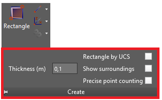
•Thickness(m) - define thickness of View Section, created by line or XY, XZ or YZ Co-planar, by entering value in meters.
•Rectangle by USC:
o When checkbox is unmarked changes UCS before creating Rectangle View Section (works as it was developed initially).
o When checkbox is marked does not change UCS before creating Rectangle View Section.
•Show surroundings:
o When checkbox is unmarked shows only points within View Section (works as it was developed initially).
o When checkbox is marked shows View Section points and surrounding of decimated
point cloud (Decimated surrounding is shown only when the View Section visualizes
all scanned points- green light bulb).
•Precise point counting:
o When checkbox is unmarked calculates points in View Section approximately, therefore provides greater performance (works as it was developed initially).
o When checkbox is marked calculates points in View Section precisely, therefore performance is much lower but in this case calculation consider whether the scan positions and logical classes are turned on/off for visibility.